Thu, 29 September, 2022
A damage mechanism review is a type of study that identifies the potential process damage mechanisms as well as the consequences of failures which making ensures that the failure hazards are sufficiently determined and analyzed. In addition, during this study, effective measures will be defined and recommended to prevent and mitigate the adverse effects and consequences of the hazards, and/or new systems are implemented to manage the hazards.
The desalting process of crude oil is imperative to ensure the good quality of crude oil, that is, to remove impurities before its transfer to refining. This process is characterized by the mass-thermal transfer of materials, which leads to the obtaining of fractions. The pre-treatment of oil from harmful impurities occupies an important place among the main processes associated with the production, collection, and transportation of oil to refineries or export. This additional pre-treatment and the manufacturing of these first fractions are carried out at the crude distillation unit as shown in figure 1. After the desalting process, the crude oil must be partially evaporated to the extent that all products except atmospheric residues must be in the vapor phase when the oil enters the atmospheric column. Thus, the furnace is required to raise the temperature between 330 and 385°C depending on the components of the crude oil.
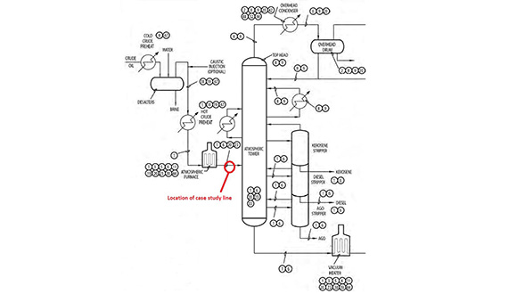 Figure 1: flow process of crude distillation unit without vacuum distillation
As shown in figure 1 with the red highlight, this case study line has been highlighted between the atmospheric furnace and the atmospheric tower (The part marked in the red circle) with the following operating and design condition.
|
Operating pressure (kg/cm²)
|
2.06
|
Operating temperature (°C)
|
345
|
|
Design pressure (kg/cm²)
|
25.8
|
Design temperature (°C)
|
380
|
DAMAGE MECHANISM REVIEW & INSPECTION PLANNING
The TWI CS was requested to evaluate the remaining life of the crude oil outlet line from the furnace in the crude oil distillation unit during the shutdown. For achieving the study objectives, in the first step, TWI's engineering team performed a preliminary damage mechanism investigation based on the existing P&ID, PFD, and heat material balance sheet (H&MB) and also used standards API 571. As a result, the following damage mechanisms were determined in the first step to determine the inspection plan.
- Sulfidation
- Erosion/Erosion – Corrosion
- Naphthenic Acid Corrosion
- Chloride SCC
Since there was no ISO drawing for this line, a manual ISO drawing was prepared in the second step as shown in Figure 2. Then, TWI's engineering team determined 20 condition monitoring locations (CML) based on API 570 and API 574.
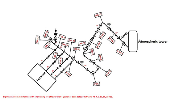 Figure 2: Manual ISO drawing with condition monitoring locations (CML)
Considering the study result, the four below-mentioned inspection methods were determined and carried out for identifying the general internal and external integrity of the pipes as the most susceptible areas to corrosion threat.
INSPECTION RESULTS & RLA
During inspections, the TWI’s inspectors detected six locations with significant internal metal loss. The PAUT (B-scan file) is shown in Figure number 3 to 7 as a sample.
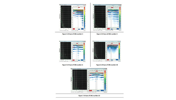 Figure 7: B-Scan of CML number 19
The TWI CS engineering team performed the Remaining Life Assessment (RLA) to determine the corrosion rate (CR), required thickness (MRT), and remaining life (RL) for these 20 CMLs based on the API 570 standards, inspection results as well as design data.
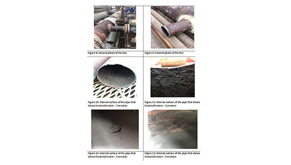
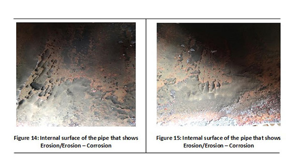
The six inspection locations were detected with a remaining life of fewer than 5 years during RLA. After the inspection results were interpreted by the inspectors and consulted with the engineering team, it was determined that the main reason for the reduction in thickness is due to Erosion/Erosion - Corrosion. In this regard, these CMLs were determined as critical findings and it was also recommended that these locations be replaced as soon as possible. The photos taken after the cutting operation clearly showed that the internal surface of the pipe was severely under Erosion/Erosion – Corrosion (Figures No. 8 to 15).
EFFECT OF FLUID VELOCITY AND REYNOLDS NUMBER ON EROSION/EROSION – CORROSION
Two important and fundamental factors in the investigation of Erosion/Erosion- Corrosion are as follows:
- Fluid velocity
- Reynolds number (As equation 1)
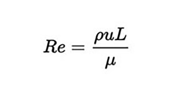 Equation 1
Re= Reynolds number
Ρ= Density of the fluid
μ= Dynamic viscosity of the fluid
u=Fluid velocity
L= Inside diameter
The distribution of Reynolds number and also fluid velocity along the pipe is as following chart:
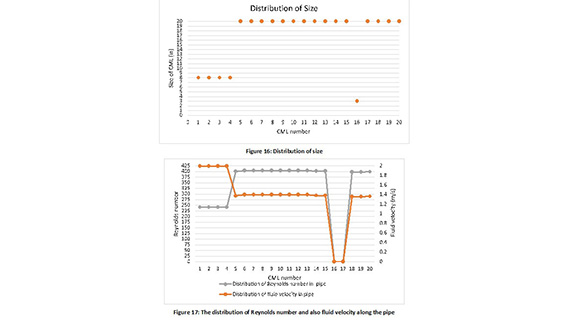 Figure 17: The distribution of Reynolds number and also fluid velocity along the pipe
According to the PAUT result, three of the critical finding along the pipe is in CMLs 6, 18, and 19. Considering Figure 18 location of these three CMLs exactly is in the impingement location where fluid from the 8” pipe transfers to the 20” pipe. According to the diagram in Figure 17, the fluid enters from the 8" pipe to the 20"pipe with a velocity of 1.9 m/s and a temperature of 345 ̊C, while in this area in the 20" pipe, there is severe turbulence in the fluid. As can be seen in diagram figure 17, the Reynolds number in this area is almost 400. This has caused severe Erosion/Erosion- Corrosion in this area.
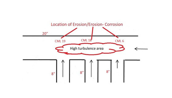 Figure 18: Schematic of impingement location in 20” header pipe
THE EFFECT OF IMPROPER VALVE TYPE INSTALLATION ON EROSION/EROSION-CORROSION
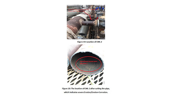
The valves installed on the 8" line were gate valves. Gate valves are usually used as on/off valves so they should be either fully open or fully closed but upon visual inspection, it was found that on the 8" line the gate valves were partially open which caused the Two areas (CMLs 2 & 4) in the 8" line just after the gate valves have severe internal corrosion. The cause of this severe corrosion can be attributed to the diagonal collision of the flow with the upper surface of the pipe (Figures 19 & 20).
 Hamidreza Saadat
TWI Caspian Sea Technical Manager
Hamidreza Saadat
TWI Caspian Sea Technical Manager
Plant Inspection, Risk Assessment and Damage Mechanism Review, Welding Inspection, Asset Integrity Management, and Fitness for Service Assessments Leader and Lecturer.
For further information about TWI CS’s Engineering Services please contact email CRM@twi-cs.com, or (012) 404 32 00/01